FlashProfils project manager
In FlashProfils, all the steps for creating and editing a project are done via the Project Manager.
The left side of the project manager shows in chronological order a list of steps needed to go from the selection of the horizontal alignment to the calculation of the cut and fill quantities. Each step will be made only if the previous step has been. The ![]() symbol indicates a stage already completed, while the
symbol indicates a stage already completed, while the ![]() symbol indicates a pending step.
symbol indicates a pending step.
The right side of the Project Manager displays various information specific to the current step, and allows access to different commands of this step.
Using the Project Manager, you will define the horizontal alignment, create the profile stations, and draw the Longitudinal Section and Cross Sections of the natural terrain at different scales and comparison planes.
You will then build the DESIGN Longitudinal Section as well as the Typical Cross Sections to finally calculate the cut and fill quantities.

Horizontal alignment, profile stations.
After creating the horizontal alignment (from a 2D polyline, a line or an arc), you will place stations on this alignment: at the ends of the segments, at regular intervals and at strategic points that you determine.
You can also vary the length of the profiles by adjusting or extending the profiles on objects that serve as a support line.
Once this step is done, you will be able to start the calculation that will create the longitudinal profile and cross sections across the natural terrain. You will be able to draw the profiles thus created.

OGL Longitudinal Section

OGL Cross sections
FlashProfils allows to visualize and draw OGL Longitudinal Section at different scales and comparison planes, while specifying the elements to appear in the cartridge.
The cartridge is fully configurable. You can change the labels, text sizes, colors, choose a scale in X and Y, indicate a fixed or self-calculated comparison plan.
In the same way, FlashProfils allows to visualize and draw OGL Cross Sections at different scales and comparison planse.
Once this step is done, you will be able to create the Design longitudinal section directly on the OGL Longitudinal Section, as well as the Typical Cross Sections which will apply on the OGL Cross Sections .

Creation of the Design Longitudinal Section

Creation of a typical cross section
Design Longitudinal Section
This command allows you to create the DESIGN Longitudinal Section (also called vertical alignment) directly on the titleblock of the OGL longitudinal section : click the waypoints, then enter the lengths and slopes of the segments. You will then be able to indicate the radii of the circular connections if necessary.
Typical Sections
This command lets you create and edit Typical Sections, while viewing OGL cross sections of the current project.
A typical section is always composed of a Design line (the topmost line, iitself comprising one or more segments), a Subgrade line (the bottom-line, also comprising one or more segments) and 2 "virtual" lines representing the catchslopes in a cut condition and in a fill condition.
In addition, a typical section can contain variables points that allows to vary the length, the slope (or both) of the segments of the Design line or the bottom line.
A typical section can contain one or two sides, symmetrical or not.

Assigning typical cross sections
This command allows you to assign Typical Sections to the OGL Cross Sections, change the application length of each Typical Section, select the sill polylines for variable points, and finally calculate the cut and fill quantities.
You must initially assign a typical section to each of the cross sections of the natural terrain. You can if necessary change the application length of a typical section. Then, if you use typical section containing varyiable points, you must attach each variable point to a polyline on which the section will lean . This is optional and, if you do not select the polyline, variable points will simply be ignored.
Then indicate the average thickness of topsoil removal and if it must be calculated on the typical section width only.
Finally, indicate the elements to create in the drawing : the polylines representing the endpoints of the typical profiles, polylines representing the OGL catchpoints , polylines representing the typical profiles on the natural terrain, and the hatches representing the volumes of cut and fill quantities.

Simple road
After the calculation, two files are created : the file of the cut/fill quantities calculation, and the file of the catchpoints layout. You can view these files through the project manager.
In the drawing, the 3D polylines representing the ends of the typical profiles will be created, as well as the 3D polylines representing the entry points of the profiles and the 3D polylines representing the typical profiles on the TN.
You can then use these polylines to create a new DTM.
get_app |
Download FlashProfils 2.0 |
| To receive FlashProfils download link by e-mail, please fill in the fields below: (Available for AutoCAD and BricsCAD) | |
shopping_cart |
Buy FlashProfils 2.0 - 469.00 € TTC |
| Get a license on the secure payment site Paypal | |
Enter the serial number of the software, then click 'Pay now'. You will be redirected to Paypal.com website to register. You'll then receive your license code by e-mail within minutes. (Make sure your anti-spam filter doesn't block messages from DeliCAD.com). |
|
info |
Additional Information |
| Help - More information | |
You want more information on this application or on the site, on the means of payment or the purchase of several licenses, do not hesitate to contact me. |
|
![]()
![]()
(C) DeliCAD.com - Add-ons for AutoCAD, BricsCAD, ZwCAD in topography, architecture, mechanics
Entreprise Individuelle Philippe Sérange
21 rue du Batifois
63500 Issoire - Puy-De-Dôme (63)
RCS Clermont-Ferrand 478 467 814
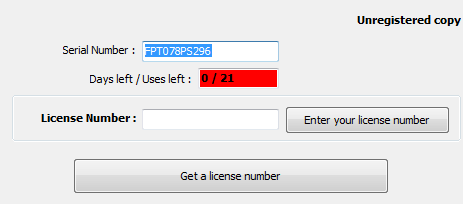
To find your serial number, click the 'Help' button (![]() ) of the add-on toolbar.
) of the add-on toolbar.
A dialog box displays, showing this number (in blue) :